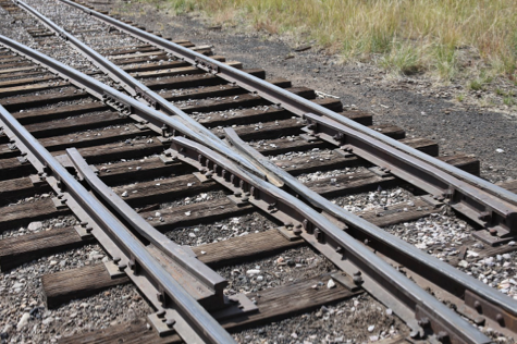
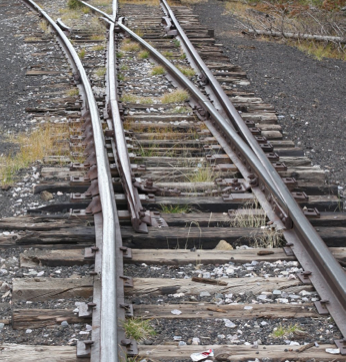
The Tracks and Turnouts of the Denver & Rio Grande Narrow Gauge
by Christian Romberg (Christian.Romberg@googlemail.com)
This article was first published in the “Hp1 Modellbahn” magazine of the FREMO model railroad club, issues 4/2010, 1/2010, 3/2010 and 1/2011. Because the article was published in German, I’ve decided to translate it into English to make it available to a wider audience. Also the article was written with the German model railroader’s attitude in mind and I’ve not adjusted the article e.g. for the American model railroader, where handlaying track is much more common. The target audience is the modeler who wants to build prototypical tracks and turnouts or anyone interested in trackwork.
Also note, that in this article, “turnout” refers to the whole assembly, while “switch” only refers to the part of the turnout, where the points are located.
Introduction
It is rails that defines a railroad. Despite that, modeling tracks and turnouts does not have the same priority for many model railroaders and manufacturers compared to cars and locomotives. To decide which compromises one is willing to do, first knowledge of the prototype has to be acquired.
At this point model railroaders, who model Deutsche Reichsbahn Gesellschaft (DRG; pre-war), Deutsche Bundesbahn (DB, post-war Western Germany) or Deutsche Reichsbahn (DR, post-war Eastern Germany) can consider themselves very lucky. In a stereotypical way, German engineers specified every turnout till the very last nut and bolt. But even more: real-life tracks and turnouts built according to these specifications totally follow these plans!
Unfortunately it’s not that easy with American railroads. Apart from the sheer number of different railroads, the MoW (Maintenance of Way) plans were often just used as a sketch by the men building the tracks and turnouts.
Currently (end of 2009), the FREMO HOn3 subgroup is forming for modelers of American 3’ (914mm) narrow gauge railroads of Colorado and New Mexico. Apparently, the D&RGW (Denver & Rio Grande Western) will play a dominating roll here. For this reason and because I had the opportunity to do research at the location, I would like to provide information about the trackwork of the D&RGW narrow gauge railroads in this article.
The D&RGW operated a huge narrow gauge network in the Rocky Mountains of Colorado and New Mexico, with curve radiuses down to 24 degrees1 (i.e. a radius of 240.49’ or 73.30m). Today two sections of this network have been preserved: the Durango and Silverton Narrow Gauge Railroad in Durango, CO (www.durangotrain.com) and the Cumbres and Toltec Scenic Railroad between Chama, NM and Antonito, CO (www.cumbrestoltec.com). Both are worthwile travel destinations. The following describes the state of the track in the timeframe 1940 till 1969. Actually most of the track present during that time had been laid even earlier in the 1920s and 1930s.
Used units and terms
Many measurements in this article are metric, table 1 contains all units relevant to this article. Numbering ties starts at the headblock, the headblock ties are numbered 1 and 2, respectively. The notation 17|18 means: between ties 17 and 18. 30lbs rail means: 30 lbs/yd rail.
Ties
The ties have a cross section of (HxW) of 6”x8” (15.25cm x 20.32cm), regular ties have a length of 6’ (182.88cm), ties for turnouts are longer (see below). The alignment of ties is not perfect, there is often a slight displacement to either side, or occasionally a noticable tilting.
It seems that 30’ long sections of rail were most common, 16 ties were used for such a section, resulting in a distance of 22 1⁄2″ from mid of tie till mid of tie. For 33’ long sections of rail a distance of 22” and for 39’ long sections of rail a distance of 21 1⁄4″ had been defined.
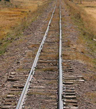
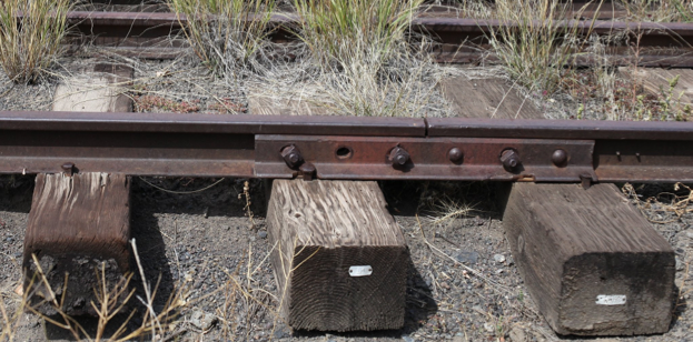
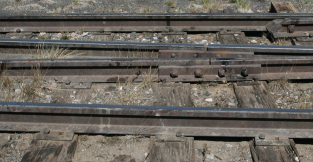
The joint bars for the left and right rail are off by half a rail length, clearly visible in figure 1. The rail joint is normally placed between ties, only exceptionally on a tie. There are shorter and longer joint bars (figures 2 and 3).
Rails
When the narrow gauge railroads were initially built in the 1880s, very light rail profile (e.g. 30 lbs/yd) was used. Later this was replaced by heavier profile at many places. For example in 1922/23 between Antonito, CO until close to Osier 70 lbs/yd rail was laid. In 1936 85 lbs/yd rail was laid on the rest of the line to Chama, NM (mileposts 316.87 to 342.53). Some sidings have 65 lbs/yd rail.
In 1947 significant portions of the network were equipped with 70lbs and 85lbs rail as well as 90lbs, 75lbs and 65lbs rail. Some shorter portions were equipped with 60lbs, 57lbs, 52lbs, 45lbs, 40lbs and 30lbs rails.
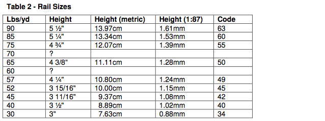
On the Rio Grande Southern (RGS), 60lbs, 57lbs, 52lbs and 40lbs was most common, but also 56lbs and 45lbs rail was used. Table 2 lists the height of the rail for the respective weights. This height is specific for the D&RGW and might be different for other railroads.
Tie Plates
On the main track between Antonito and Chama tie plates have been used though some sidings on that section and some tracks in the Chama Yard don’t have tie plates. For example, there are no tie plates at the small station at Gato, CO, not even at the turnouts. Figures 2 and 3 show close-ups of the rail fastenings. Tie plates used on narrow gauge railroads are relatively small and do only have 4 spike holes.
Ballast
There is a wide variety in ballast material and color. Gravel has been used as ballast, at some locations, or to repair spots, also cinder. Locally available material also has been used as ballast, e.g. vulcanic material or rounded river stones. On some photos it also looks like dirt. Generally the ballast was relatively fine grained or also sandy, coarser stones or even “modern” ballast were rare. Common colors were dirtlike brown and gray, or dark gray
Some turnouts, especially those in the Chama Yard, have parts of their ties buried under ballast. On other places, sometimes the tie ends are totally exposed (figure 2)
Turnouts
For turnouts of American railroads, the curve ends before the frog, the frog itself is straight. Respectively, the diverging angle is specified as the number (#) of the frog. For example, for a #6 turnout, the diverging track departs 1 foot to the side for each 6 feet of length, assuming the diverging track is straight. In comparison, a #15 is much more shallow, the diverging track only departs 1 foot to the side for each 15 feet of length of the main track.
American turnouts provide one big advantage and one big disadvantage for the modeler. The advantage compared to German turnouts is, that the points are formed from the same profile as the main track. Also the points are connected in a fixed way by a rod, i.e. both points move simultaneously. This is very different from the extremely complex German “Klammerspitzenverschluß”. The disadvantage is, that the frog is in most cases not built from regular profile but made from cast iron or steel. Fortunately for narrow gauge railroads like the D&RGW, the frog is normally made from regular rail and the guard rails also.
Narrow gauge turnouts are relatively short, the D&RGW preferred #81⁄2 turnouts, also #10 were used. So if you’re considering building your own turnouts, only the additional time and effort but not the space should be a reason, not to do so.
In the search for a typical turnout
The D&RGW has a MoW plan for narrow gauge turnouts (plan 115.4) However, a comparison with about 20 existing turnouts has revealed, that the tie layout of this plan has nothing to do with the tie layout of real life turnouts. At least the rest of the geometry is according to the plan.
So I had no other choice than to search for a real “typical” turnout and take the measurements myself.
This turnout should not be a curved turnout, should not be to close to other turnouts (so that e.g. ties don’t overlap), should be a #8 1⁄2, should possess 29 ties from headblock to the point of frog (PoF), because this is the most common tie arrangement. Additionally the details should not be buried too deep under ballast.
Of course this raises the question: Is the track in the same state as about 40 years ago when the D&RGW ceased operation here?
The (new) station in Antonito has been built after that. Most turnouts in the Chama yard seem to be original. Probably some ties have been replaced, which would not change their position but possibly their length, because ties were not necessarily replaced by a tie of the same length.
The remains of the small station of Gato, CO (aka Pagosa Junction) can be found west of Chama, within the Southern Ute reservation, It seems that there were some differences between the Southern Ute and the D&RGW demolition squad, so some of the tracks there were not removed. This would provide the chance to look at turnouts, which have definitely not been modifed since. Interestingly, both turnouts there and most of the other ties don’t have tie plates. It could be confirmed, that 29 ties from headblock to point of frog is typical. Unfortunately trespassing is not permitted, so I could not take measurements of these turnouts.
I’ve found the typical turnout then in the
Chama Yard. It is turnout #41, located at the
start of the wye. Figures 4, 5 and 6 show
this turnout. The drawing shows the actual
tie layout, only the railhead is shown. One
can imagine the ideal tie layout from this.
Normally all ties are supposed to be at a
right angle to the main track. Also there are
blocks of ties of the same length, every block contains longer ties than the previous one. Many actual turnouts have a more regular tie spacing at the switch section compared to turnout #41.
Typical Variations: Frog
Originally, 15’ long frogs have been used for #8 1⁄2 turnouts, later also 16’6″ long frogs. The drawing shows a 15’ frog (6’5 1⁄4″+ 8’6 3⁄4″, 196,2 cm + 261,0 cm). A 16’6” frog is about 226 cm + 277 cm long, i.e. about one foot (30cm) longer at the throat and about half a foot (16cm) longer at the heel. Figures 9, 10 and 11 show a relatively young 16’6” frog, in difference to most frogs it has a manufactures plate.
A 15’ frog starts at ties 25|26 and ends at ties 34|35. Different types of tie plates have been used, some frogs have a distance piece at the throat, others not (figures 5 and 12). The ends of the rails at the frog are sometimes beveled, sometimes not.
Fig. 7 – points, stock rail bend
Fig. 8 – rail brace
6
Fig. 9 – 16’6″ frog
Fig. 10 – manufacturer’s plaque
Fig. 12 – frog
Fig. 11 – 16’6″ frog
7
Typical Variations: Tie layout
As a basic principle, ties are positioned at a right angle to the main track. Also ties are getting groupwise longer, e.g. first 3 ties of length 6’, then 7 ties of length 6’6” and so on.
In real life ties are often a bit tilted and displaced to the left or to the right.
Which blocks of which length of ties a turnout has, varies from turnout to turnout. Often not all ties in a block (see turnout #41) are of the same length.
For a #8 1⁄2 turnout 29 ties from headblock to point of frog was the most common configuration. Some do only have 28 ties. 30 ties or less than 28 ties are exceptional. Table 3 summarizes my observations.
The total number of ties counting from the headblock varies between 37 and 42. The less ties, the earlier the regular ties of the main and diverging track are interdigitated.
Table 3 – Tie Lengths (from observations)
|
Length |
Number |
Comment |
|
13′ or 14′ |
2 |
headblock |
|
6′ |
0-3 |
|
|
6’6″ |
7-10 |
Till tie 11 or 12 |
|
7′ |
3-6 |
|
|
7’6″ |
1-2 |
|
|
8′ |
4-6 |
|
|
8’6″ |
0-3 |
|
|
9′ |
0;3-4 |
|
|
9’6″ |
2-3;5 |
Point of frog on tie 29 (or 28) |
|
10′ |
0-2 |
|
|
10’6″ |
1-5 |
|
|
11′ |
0-3 |
|
|
11’6″ |
2 |
|
|
12′ |
2 |
Typical Variations: Switch
Points are normally straight (straight switch), which means the curve starts after the points. As a consequence the outer rail of the diverging track has a bend about 8 1/8″ before the points start and continues straight from that until the end of the point, reaching a point heel spread of 5 3⁄4″.
The points end at ties 10|11, after that the curve starts which ends at the start (throat) of the frog. The point starts 1 1⁄2″ before mid tie of tie #1.
Some turnouts gave me the impression, that the builders started the curved rail right at the beginning and also bend one point accordingly.
Different types of switch rods can be found, also either 2 or 4
switch rods were used (figures 6 and 7)
The switch has 8 or 9 rail braces (figure 8) on both sides, also sliding plates are used under the points. In Gato there is one turnout without tie plates which has 6 rail braces only on both sides
A few turnouts have distance pieces at the heel of the points between point and outer rail, most have not. Figures 14 and 15 show a low and a high switch stand, which is located on the headblock.
Typical Variations: Guardrails
The guard rails are often 8’3″ long, the bend at the ends is 2’6″ long, sometimes the end of the rails are beveled. Often 2 or 3 rail braces are used on the inside, sometimes one rail brace is even
Fig. 13 – guard rail, rail clamp
8
placed at the outside (figure 12). Besides guard rails without rail braces (see turnout #41, figure 5), there are also turnouts which use rail clamps instead (figure 13).
Turnout #41 has a slightly shorter guard rail: c. 221cm. In theory (plan 110), the mid of a 8’3″ guard rail is displaced 5″ to the point of the frog.
Typical Variations: Rail sections within the turnout
Normally the stock rails start 3 ties before in front of the headblock, sometimes 2 or 2.5 ties. Turnout #41 has 33′ long stock rails, the first stock rail ends at tie 17|18, the second one at 36|37.
Also frequently seen: first stock rail ends at 16|17, second one ends at 34|35 (end of frog) or 37|38.
Dual gauge
Another interesting aspect of the D&RGW narrow gauge is the dual gauge operation, where standard gauge and narrow gauge trains operated on the same track, which was equipped with 3 rails. Even mixed operation occurred, narrow gauge locomotives operated trains containing narrow gauge and standard gauge cars. Because of the displacement and different heights of the couplers between standard gauge and narrow gauge cars, a so-called idler car was used. This car was equipped with both couplers.
On regular track the third rail was positioned in a way that both gauges were available, i.e. 3′ (914mm) and 4’81⁄2″ (1435mm).
Fig. 15 – high switch stand
Fig. 14 – low switch stand
9
Fig. 16 – Alamosa Yard; Northern Arizona University, Cline Library, Tad Nichols collection, NAU.PH.99.3.17.10
Fig. 17 – Alamosa Yard; John West, www.narrowgaugememories.com
10
The third rail added a bit more complexity to turnouts, because instead of one frog, they had three and instead of two guard rails, they had 9. Figures 16 and 17 show some turnouts in the Alamosa Yard, the photos were taken in 1960 or 1963, respectively.
Fig. 18 – northmost turnout in La Jara, CO
As discussed before, there are no – or at least no correct – plans available, so again I had to measure a turnout myself. With the regular turnouts it had been proven very difficult to find a “typical” one. With dual gauge turnouts it has been very difficult to find one at all. Even extraordinary difficult: there is none left.
Between Alamosa, CO and Antonito, CO the third rail existed until c. 1970. The Cumbres & Toltec Scenic Railroad later moved an original dual gauge turnout along with an idler car in front of the (new) Antonito station for a small dual gauge exhibition.
This copy allows the study of the positions of the various guard rails, unfortunately, the geometry of this turnout is far from being representative. Also the ties are not visible apart from the fact, that the tie layout would not be genuine.
However, some of the turnouts which used to be dual gauge turnouts do still exist, with the third rail missing. In Antonito’s original station and in La Jara (located between Alamosa and Antonito) a couple of such turnouts do still exist, in Alamosa only a few artifacts can be found.
Similar to regular turnouts there were #81⁄2 and #10 dual gauge turnouts. But there were more variations, e.g. not every left turnout is alike, depending on which side of the track the third rail is located. The second turnout in figure 17 is a turnout, where standard gauge can go straight or turn right, but narrow gauge must turn right. All these turnouts have (today) 85 lbs/yd or 90 lbs/yd rail.
With this information at hand I could now start to reconstruct a turnout. I measured the tie arrangement of the northmost turnout in La Jara, the narrow gauge part of the track was on the Eastern side. Figure 18 shows this turnout. This #81⁄2 turnout has 41 ties from headblock till point of frog, this is even in-line with plan 115.2. The geometry of the standard gauge rails is according to plan 73.5. The location and length of ties is as found in May 2010. A “perfect” turnout would have all ties at a right angle to the main track and the ties would get block-wise longer. The D&RGW used 9′ ties on many main lines and 8′ ties on many branch lines. The regular track in La Jara uses 8′ ties.
11
All found turnouts are equipped with 15′ points and have 9 rail braces on both sides, the points end between ties 9 and 10. The special gauge plate which has a gap where the third rail was located can be seen in figure 19. The switch rod still shows the connector to the third rail, also many ties still show the spike holes. The frogs are not cast. On historical photographs often spring frogs can be seen, see the narrow gauge frog in figure 16. The found turnouts had between 41 and 44 ties from headblock to point of frog, independent of the fact, whether it was a #81⁄2 or #10 turnout. The total number of ties varied from 52 to 57 depending on position and whether it was a #81⁄2 or #10. (Numbering from headblock: tie 1 and 2 are the headblock ties)
Fig. 19 – switch section, northmost turnout in La Jara
The drawing only shows the railhead. Because it is a reconstruction and rails have been replaced since the removal of the third rail, the rail joints are not shown with the exception of both the 15’ frogs. However, that the turnout starts 3 ties before the headblock is quite common.
Geometrically two 15′ frogs of a #81⁄2 don’t fit in a row. My assumption is, that one rail of the narrow gauge frog has been shortened, but that might have been different for every dual gauge turnout.
7 out of the 9 guard rails were 8’3″ long, sometimes (e.g. exhibit in Antonito, last guard rail in main track) a longer guard rail was used. The guard rail at the first frog is asymmetric. Measured at the exhibit in Antonito the bend ends are 10.6″-11.4″ (27-29cm), the first part is c. 6’4.8″ (195cm) and the second part c. 5’8.9″ (175cm) long.
One guard rail, visible on the drawing if looking carefully, is c. 4″ (10cm) shorter because of the tight space.
Stub switches
Stub switches (aka “stub turnout”) are a very old fashioned turnout design. In comparision to a “modern” turnout, it does not have points, instead the main rail bends, which could only be done with relatively light weigth rail.
In Rockwood, CO a genuine stub turnout has survived. It is located in the Wye of the station of the Durango and Silverton Narrow Gauge Railroad. The rail of the turnout is marked with the manufacturing year 1887 and the frog bears a stamped 81⁄2 and 50, which means it is a #81⁄2 turnout with 50 lbs/yd rail. The measured rail height is 3.86″ (9.8cm), It is very likely that the turnout was built in or not long after 1887.
12
This turnout is a right-hand turnout. Figures 20 and 21 show, that this turnout contains distortions. Furthermore the main track starts curving right after the frog. The outer rail of the diverging track is continuously bent, normally the curve ends before the frog. Because the frog is straight this turnout is not free from geometrical contradictions.
Figures 22, 23 and 24 show details of the switch mechanism.
This turnout is from a time where tie plates were only rarely used. Like the track around the turnout only some ties are equipped with tie plates, these are shown in the drawing (the other drawings don’t show tie plates because all ties have them)
The 7 ties in front of the headblock have slide plates, regular tie plates have been used for them. This is the section where the rail is bend.
The drawing shows the turnout without the distortions. Also the curve in the main track and diverging track are not shown, instead the dotted line shows the “ideal” rail position. The tie arrangement is as actually found in May 2010. All drawings do only show the rail head: 0.7mm wide for 70 and 90 lbs/yd rail and 0.6mm wide for 50 lbs/yd rail in 1:87 scale.
Fig. 20 – Rockwood stub switch
Fig. 21 – Rockwood stub switch
13
Where to get parts
To my knowledge prototypical turnouts are not commercially available, so you need to build your own. The code 55 track from Micro Engineering is pretty close to the prototype. The tie width is about 7.5” (prototype: 8”) and the distance from mid tie to mid tie is about 21.25”. However the ties are about 2mm too long. The tie plates look very prototypical, because narrow gauge railroads did actually use the small tie plates. So to get prototypical track you will need to cut of 1mm on each side of the tie.
The Proto 87 Store (www.proto87stores.com) offers the following parts:
- etched tie plates for regular ties and tie plates for turnouts
- code 55 rail profile
- etched spikes (notabsolutely required)
- rail joints for code 55 (ask for them if not listed in thecatalogue)
- switch rods
- nuts and bolts, rail clamps Various nuts and bolts are availablefrom Grandt Line Products.Micro Engineering wood ties are often a bit too wide, but normally there are enough slim ones in a bag.It might be possible to create rail braces from Exactoscale (http://www.exactoscale.co.uk) rail chairs: “4mm scale 3hole S1 chair”
Fig. 22 – Rockwood stub switch
Fig. 23 – Rockwood stub switch
Fig. 24 – Rockwood stub switch
14
Figures / References / Acknowledgements:
Fig. 16: Northern Arizona University, Cline Library, Tad Nichols collection, NAU.PH.99.3.17.10 Fig. 17: John West, www.narrowgaugememories.com
All other figures and all drawings: Christian Romberg
MoW plan numbers refer to the D&RGW Maintenance of Way book, 1966 edition Thanks to all people who shared knowledge in several discussions on ngdiscussion.net
All CAD drawings were made with QCAD Professional, if anyone wants the DXF files, let me know, however, there are known issues when importing them with AutoCAD.
Revision history
January 20th, 2011; Initial Public Version 1.01
Feedback
Send feedback to Christian.Romberg@googlemail.com
15

